
BRL-CAD: An Open Source Solid Modeling System From the U.S. Army
BRL-CAD is the U.S. military’s primary system for solid modeling in computer-aided design (CAD). Its roots trace back to the MAGIC computer simulation program, which was developed in 1968 by the Mathematical Applications Group, Inc., to analyze vulnerabilities in military vehicles [5]. In 1979, Mike Muuss of the U.S. Army Ballistic Research Laboratory (now the Army Research Laboratory) at Aberdeen Proving Ground in Maryland created the first version of BRL-CAD as a tool to facilitate the simulation and analysis of combat vehicle systems and environments; this preliminary effort marked a shift from punch cards to digital modeling [3]. Unified development began in 1983, followed by a public release in 1984 [1].
As such, BRL-CAD is the oldest public version-controlled code repository in the world. Since its debut, the system has evolved into a suite of more than 400 tools that support a wide range of geometric representations. It is rooted in constructive solid geometry but also allows for uniform B-spline surfaces, non-uniform rational B-splines, n-manifold geometry, and faceted mesh geometry [1]. Application areas include defense, medicine, mechanical design, and education. Today, the U.S. military utilizes BRL-CAD extensively for vulnerability and lethality analyses of ballistic weapons systems; the U.S. Army Combat Capabilities Development Command maintains the software.
“Being a jack-of-all-trades for geometry, we need to support it all,” lead BRL-CAD software architect Christopher Sean Morrison said. “Our priorities are to close the gaps between things that cannot be represented, converted, or analyzed effectively. The CAD industry does not make that easy; there are lots of formats and representation types.”
In 2004, Morrison seized the opportunity to accelerate code development by acquiring more partners and successfully advocating for the code to be made open source. “[This] lifted the shackles on development, enabling rapid growth with no real downsides,” he said.
Now, BRL-CAD has global contributors and regularly participates in the Google Summer of Code and various university capstone projects. In fact, the system’s ability to run in parallel on Windows stems directly from an open source contribution made by high school students.
BRL-CAD presently serves as a fundamental component of the U.S. Army’s Advanced Joint Effectiveness Model (AJEM): a joint forces modeling scheme that predicts vulnerability and lethality in threat and target interactions. The U.S. Department of Defense (DOD) has integrated BRL-CAD into a suite of software tools to estimate the probability of kill for systems that are under a ballistic threat. The Fast Shotline Generator employs BRL-CAD to generate shotlines (i.e., rays through a target) that the Computation of Vulnerable Area Tool (COVART) then utilizes to evaluate penetration, component damage, and overall vulnerability [2]. “The vulnerability analyses used by the DOD have become much higher order and higher fidelity,” Morrison said. “Modern vehicles are far more complex, with action-reaction systems and redundancy.”
BRL-CAD’s unique ray tracing engine is crucial to this type of vulnerability analysis. The engine is built on BRL-CAD’s flagship librt library, which manages geometry loading, spatial partitioning, and ray-target intersections. While it can render accurate images as well, the library’s primary role is to support other programs in simulating the path of ballistic weapons that may strike military vehicles.
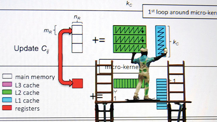
More recently, Morrison has been working to upgrade this ray tracer by incorporating modern techniques like advanced spatial partitioning and optimization methods for cache management, central processing unit performance, and distributed computing. These improvements have reduced analysis times by more than half, significantly boosting BRL-CAD’s performance. The ray tracer is now capable of processing tens to hundreds of millions of rays for highly detailed analysis; in tandem, the team is also developing a real-time ray tracing interface.
Morrison remarked that BRL-CAD is typically three to six orders of magnitude faster than other CAD systems when conducting ray tracing and loading the extremely detailed geometries of military vehicles. For instance, he tested one commercial package that loaded a geometry model in 30 minutes and shot roughly 1,000 rays per second; in contrast, BRL-CAD opened the same model in five seconds and shot from 100,000 to over a million rays per second. This dramatic difference in performance greatly expands the analytical possibilities of tools such as COVART. “Supporting an entire assessment in core memory is hard for most CAD engines to handle,” Morrison said. “A unique aspect of BRL-CAD is the efficiency with which librt represents geometry in memory.”
However, Morrison noted that one must continually evaluate the tradeoffs between speed and accuracy. The team has been incorporating graphics processing units to speed up computations for almost 10 years, but they have not yet been able to guarantee accuracy. “Is it accurate, or just 100 times faster?” Morrison asked.
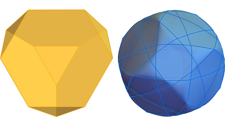
![<strong>Figure 1.</strong> Intersection distance calculations of a ray with a sphere from the original MAGIC computer code. Figure courtesy of [4].](/media/giyhpkv3/figure1.jpg)
A key calculation in ray tracing involves determining the distances from the ray’s starting point to the entry and exit points on an object, such as a sphere. Figure 1 illustrates this process [4]. Rays are cast from a central grid plane that is aligned with the target’s orientation and defined by parameters like grid size, cell size, and attack angle. Given an azimuth angle \(\alpha\) and elevation angle \(\theta\),
\[\begin{eqnarray} W_{B_x}&=&-\cos\alpha\cos\theta \\ W_{B_y}&=&-\cos\alpha\sin\theta \\ W_{B_z}&=&-\sin\theta, \end{eqnarray}\]
where the azimuth and elevation angles are measured in the positive axis direction. When both azimuth and elevation angles are set to \(0^{\circ}\), the rays are fired head-on at the target. Changing the azimuth to \(90^{\circ}\) positions the attack from the target’s left side, while setting the elevation to \(90^{\circ}\) indicates an attack from directly above.
We can calculate the intersection distances \(R_{\textrm{in}}\) and \(R_{\textrm{out}}\) by simultaneously solving the ray equation and equation of the intersected geometrical shape. The ray equation is
\[X=\mathbf{XB} + \mathbf{WB} \cdot S \tag1,\]
where \(\mathbf{XB}=(x_B, y_B, z_B)\) is a fixed point on the ray and \(\mathbf{WB}=(W_x, W_y, W_z)\) are the direction cosines of the ray. For any value of the scalar \(S\), this equation will yield a point \(X=(x,y,z)\) along the ray.
The equation of a sphere with radius \(R\) about the point \(\mathbf{V}=(V_x,V_y,V_z)\) for any point \(X\) on the surface is
\[(X-\mathbf{V})^2=R^2. \tag2\]
Substituting the \(X\) from \((1)\) into \((2)\) results in
\[(\mathbf{XB}+\mathbf{WB}\cdot S-\mathbf{V})^2=R^2,\]
\[S^2(\mathbf{WB})^2+2S (\mathbf{XB}-\mathbf{V}) \cdot (\mathbf{WB})+(\mathbf{XB}-\mathbf{V})^2-R^2=0.\]
We must then solve for the constant \(S\) to find the distances to the entry and exit intersects.
Next, we relabel the coefficient of the \(2S\) term in the quadratic expression as
\[B=(\mathbf{XB}-\mathbf{V}) \cdot \mathbf{WB}\]
and the constant term as
\[C=(\mathbf{XB}-\mathbf{V})^2-R^2.\]
The solution for \(S\) is thus given by
\[S=-B\pm \sqrt{B^2-C}.\]
If \(B^2-C<0\), no real intersection occurs. But if \(B^2-C=0\), then the ray is tangent to the sphere:
\[\begin{eqnarray} R_{\text{in}}&=&-B-\sqrt{B^2-C} \\ R_{\text{out}}&=&-B+\sqrt{B^2-C}. \end{eqnarray}\]
Verification and validation are essential to BRL-CAD; in analytical applications, they may even mean the difference between life and death. Morrison explained that the development team has dedicated much of the past year to such efforts — a key strength that sets the system apart from other CAD tools and content modelers, such as Blender or Autodesk Maya. “Our focus on fidelity is pretty intensive,” he said. “We spend an incredible amount of time validating that a ray fired at a geometry hits it when it should hit and misses it when it should miss, and that there are no geometric issues even when the geometry is corrupt or fundamentally flawed. We pride ourselves on the behavior of our code being more scrutinized than any other system.”
Geometry conversion is closely linked to fidelity, and Morrison and his colleagues have developed dozens of converters. “Our intent is to be this sort of Swiss Army knife of conversions that have awareness of analytic properties,” he continued. “We must be able to [determine] whether the mesh is well-formed, without holes or dangling triangles. If there are errors, we need routines for eliminating them.”
The BRL-CAD group recently received multiyear, multimillion-dollar funding from the DOD to support the open source development of a STEP file converter, as obtaining access to this ISO standard involves significant cost. “STEP is often referred to as the ‘yin’ of all CAD formats because of its vast complexity and ability to represent nearly everything in CAD,” Morrison said. “Before BRL-CAD’s work [on this converter], no open source STEP file importer was available.”
Another significant focus area is geometry management, which allows for the cataloging, batch processing, conversion, indexing, and visualization of large volumes of files. One prospective usage could be the preparation of multi-format files for three-dimensional printing without the need to open each one individually. “We have various customers who use BRL-CAD and have anywhere from dozens to tens of thousands of geometry files,” Morrison said. “We put a lot of time and effort into creating tooling [to manage these files].” He noted that whereas other CAD systems might support one or two formats, BRL-CAD is unique in that it supports about a dozen.
Finally, Morrison hopes to make BRL-CAD even more user-friendly overall. “For decades, the program was used by experts who could call on experts if they had issues,” he said. “So [usability] has not had much attention until recently; fundamental data structures have had to change.”
References
[1] BRL-CAD documentation. (n.d.). About BRL-CAD. Retrieved from https://brl-cad.github.io/docs/index.html.
[2] Defense Systems Information Analysis Center. (2019). Vulnerability toolkit. Retrieved from https://dsiac.dtic.mil/models/vulnerability-toolkit.
[3] Gruber, W., Nagel, R., Goldstein, R., Mittelman, P.S., & Kalos, M.H. (1967). A geometric description technique suitable for computer analysis of both the nuclear and conventional vulnerability of armored military vehicles (Technical Report MAGI-6701). White Plains, NY: Mathematical Applications Group, Inc.
[4] Naval Weapons Center. (1971). MAGIC computer simulation analyst manual part I (Final Technical Report TN 4565-3-71, Vol. II). Aberdeen, MD: Joint Technical Coordinating Group for Munitions Effectiveness.
[5] Peddie, J. (2019). Ray tracing: A tool for all. Cham, Switzerland: Springer Nature.
About the Author
Aaron Hagström
Journalist
Aaron Hagström is a journalist and graduate of the Annenberg School of Journalism at the University of Southern California. He mainly writes about mathematics and technology and is based in Minneapolis-Saint Paul, Minnesota.
Related Reading

Stay Up-to-Date with Email Alerts
Sign up for our monthly newsletter and emails about other topics of your choosing.
