Feynman’s Flying Saucer: The Second Serving
In the December 2019 issue of SIAM News, I offered an explanation of Richard Feynman’s observation on the wobble of a plate in free flight when launched with a spin around its central axis. Feynman noted that the plate wobbles twice as fast as it spins in the limit of small wobble (he actually states that the ratio is the other way around [3], but I think it is safe to say that he misremembered the result of his derivation). I recently came across Andy Ruina’s different, direct explanation of the effect; a much more extensive discussion and list of references to later work is available on his website [5]. His analysis is more general and does not rely on axisymmetry, as mine does.
Here I provide yet another explanation of the 1:2 ratio, this one based on making the gyroscopic effect’s role explicit. Since the spinning airborne plate is just a gyroscope, the key to the explanation is to first understand precisely how it feels to move a gyroscope when holding it by its axle. It will then be easy to understand the gyroscope’s motion when it is released, with its axis changing direction at the moment of release. This is precisely what happens to the plate when it is launched in the air.

Gyroscope as a Particle on the Sphere Subject to Lorentz “Magnetic” Force
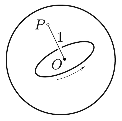
Instead of a flying plate, let us consider an equivalent object: a spinning wheel whose center \(O\) is fixed in space, with a massless axle of length \(R=1\) (see Figure 1). The axle’s endpoint \(P\) lies on the unit sphere. How does it feel trying to move this point? First, there is inertia proportional to the wheel’s moment of inertia \(I_{\textrm{diam}}\) around the diameter. More precisely, the inertial mass is
\[m = I_{\rm diam} R ^{-2} = I_{\rm diam}.\]
One could object to equating mass with a moment of inertia, but they are numerically equal if \(R\) is one unit of distance, as specified above.

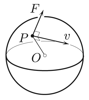
Second, if the wheel is also spinning around its axis with angular velocity \(\omega_{\rm axial}\), then point \(P\) will feel a gyroscopic force (see Figure 2). This force is normal to the velocity and of magnitude
\[F = L v, \tag1 \]
where \(L=I_{\rm axial} \omega_{\rm axial}\) is the axial angular momentum and \(v\) is the speed. It is as if \(P\) were a charged particle, with charge \(L\) moving in the magnetic field perpendicular to the sphere of magnitude \(B=1\).1 At the root of this gyroscopic effect is the fact that as we reorient \(OP\), each particle of the wheel—while confined to a sphere—is constrained to move with a nonzero geodesic curvature, thus exerting a centrifugal force upon this constraint and producing a torque; the hand that moves \(P\) feels the sum of all such reaction torques. Computing this sum, i.e., integrating over all of the body’s particles, results in \((1)\). Incidentally, it is immediately clear without any calculation that the force and velocity in Figure 2 must necessarily be orthogonal to each other; otherwise, work would have been done in spinning the wheel up or down around its axle — an impossibility since the wheel bearings are perfect.
Explaining the 1:2 Ratio
The “Lorentz” force \(F=Lv = {\rm const.}\), since \(L = {\rm const.}\) and \(v = {\rm const.}\); the latter holds because the vectors \({\bf F} \perp {\bf v}\) in Figure 2. Every trajectory thus has constant geodesic curvature \(k\) and is therefore a circle. We can find \(k\) from Newton’s second law: \(mkv^2 = F.\) Substituting \(F = Lv\) gives
\[ k = L/mv, \]
an interesting observation in its own right: the geodesic curvature of circular orbits of the axle’s tip is the ratio of the angular momentum to the linear momentum.

Let us now find the wobble’s frequency, i.e., the angular velocity \(\omega\) of \(P\) in the limit of a tight circle. Treating the small spherical cap enclosed by the tight circle as planar, the gyroscopic force in Figure 3 provides the centripetal acceleration \(\omega^2r\):
\[ \omega ^2 r = F/m = Lv/m = L \omega r/m. \]
Cancellation yields
\[\omega = L/m = \frac{I_{\rm axial}}{I_{\rm diam}} \, \omega_{\rm axial}. \]
For flat disks, \(I_{\rm axial}/I_{\rm diam} = 2\), so that \(\omega = 2 \omega_{\rm axial}\) (in the limit of small wobble). For the other extreme of prolateness, such as a pencil spun around its longitudinal axis or a rifle bullet, \(I_{\rm axial}/I_{\rm diam}\) is small and \(\omega \ll \omega_{\rm axial}\). This is also easily visible from the Poinsot description of the motion of free rigid bodies [4].
The Lagrange Top
The Lagrange top, i.e., the axisymmetric top, is treated with Euler’s angles in most books on classical mechanics (e.g., [1, 4]). But the Lagrange top is equivalent to the particle in Figure 2 with an additional gravitational force. And this equivalence allows for a more intuitive and less cumbersome analysis of the problem than the traditional one. I may provide this analysis elsewhere.
1 Actually, \(B=R^{-2}\) happens to be the Gaussian curvature of the sphere (I chose \(R=1\) only for simplicity). In fact, Gaussian curvature plays a key role in the motion of spinning tops [2].
The figures in this article were provided by the author.
References
[1] Arnold, V.I. (1989). Mathematical Methods of Classical Mechanics. New York, NY: Springer-Verlag.
[2] Cox, G., & Levi, M. (2018). Gaussian curvature and gyroscopes. Comm. Pure Appl. Math., 71(5), 938-952.
[3] Feynman, R. (1997). Surely You’re Joking, Mr. Feynman! New York, NY: W.W. Norton & Company.
[4] Goldstein, H. (1980). Classical Mechanics. Reading, MA: Addison-Wesley.
[5] Ruina, A. (2007). Rolling and Sliding of Spinning Things. Retrieved from http://ruina.tam.cornell.edu/research/topics/miscellaneous/rolling_and_sliding.html
About the Author
Mark Levi
Professor, Pennsylvania State University
Mark Levi (levi@math.psu.edu) is a professor of mathematics at the Pennsylvania State University.
Stay Up-to-Date with Email Alerts
Sign up for our monthly newsletter and emails about other topics of your choosing.


